Machined Parts and CAM Programming
- Found
- Making parts by hand showed me how much of the result is decided by the setup plan.
- Outcome
- 9 parts modeled, 5 programmed in SolidWorks CAM; programs run on Haas CNC
Manufacturing · Quality · Reliability
Manufacturing Engineer
I go to the floor, measure where the time and material are going, and fix what the data points to. Each project here starts with a problem I found, the engineering tool I used to prove it, and what changed afterward.
Map the line, time the work, find the constraint, and size the queues.
Seen in: production line · line balancing caseMake defects visible where they happen, rank them, and remove the cause.
Seen in: defect tracking · aircraft shaft · FMEADesign experiments, model the process, and say how confident the answer is.
Seen in: stent DMAIC · line simulation · bracket FEATurn a fix into floor markings, picture cards and work instructions people follow.
Seen in: floor zones · reason cards · break callsWork samples
Every project follows the same arc: what I noticed, the tool I used to prove it, why it was worth fixing, and the result. Each result says whether it was measured, calculated, simulated or only proposed.
Work samples / Production line flow
Professional projectI mapped a fully custom, made-to-order production line, where every order is different, and found that almost all of its lead time was waiting. Rebalancing the line around its slowest station raised daily output by 24%.
I walked every order from release to shipping with a stopwatch and counted the units waiting at each handoff. Only 0.26% of the lead time changed the product.
The line hit about 94% of its plan. One finishing station was 7% too slow for demand, and queues in front of it hid the real problem.
Daily queue counts and a stoppage log, a simulation to test the idea, then painted floor zones and simple move rules so people shift to where the work is.
Measured in production after the change, against the capacity baseline from the study. The simulation shows room for more.
Solid-wood products, every one built to a customer's order. Each unit passes through 17 steps: cutting and kitting, joinery machining, assembly, three rounds of sanding, two coats of finish and final QC.
Putty needs 10 minutes to set and each coat needs 20 minutes to cure. Those waits are part of the process. Anything longer than that is a queue, and queues were where the time went.
Operators explained the work and its exceptions. Managers picked the programs, and the crew made them stick.
| What | Value | How I know | Type |
|---|---|---|---|
| Share of lead time that adds value | 0.26% | Time study and value stream map | measured |
| Queue before Prep sanding vs what it needs | 2.9× | Daily queue counts vs Little's Law | measured |
| Defects per 100 units, before | 3.5 | Set-aside logging during the study | measured |
| Extra time in the first cure area | +24.5 min | Plant Simulation model | simulated |
| Daily output after rebalancing | +24% | Production count vs the study's capacity baseline | measured |
| Long-term future state | +48% | Plant Simulation future-state model | simulated |
Counting queues at the same times every day turned "there's too much on the floor" into a number for each handoff.
Counting only some queues made lead time look like hours. Counting all of them showed days.
The line didn't need more people. It needed people at the right station at the right time.
The simulation proved the idea before anything changed on the floor, and it maps the path to the +48% future state.
Work samples / Defect tracking
In daily production useRework and scrap were invisible: defective units went to a rework cart and nobody recorded why. I made every rework traceable by defect type and station, so the line can see what defects cost in time, space and material, and act on variation before it reaches the customer.
While mapping the line I followed the rework cart. 78% of kickbacks had no reason written down, and scrap wasn't traced at all.
Every rework repeats labor, holds floor space and uses material and capacity that should go to good product. Without data, nobody could say how much, or which problem to attack first.
I grouped the defects into 8 categories plus "Other" as picture cards. The station that finds a defect scans the card, then the unit, and the case is followed until it's repaired or shipped.
Every rework is now logged with its type, station and time. Supervisors follow the trends and act on variation in the line before a problem reaches the customer.
| What | Value | How I know | Type |
|---|---|---|---|
| Kickbacks with no reason, before | 78% | Case records before the cards | measured |
| Defect categories in use | 8 + Other | Card set on every scan station and at QC | implemented |
| Rework logged with type and station, after | Every case | Same case records, after the cards | measured |
| Rework and material waste visible to supervisors | In use | Live dashboard and trend reports | implemented |
Rework and material waste are now visible by category, showing the labor, floor space and material defects take from the line.
A Pareto by defect type and station points improvement work where it pays most.
Trends by station show when a process starts to vary, so it's corrected before defects reach the customer.
Defects tied to material waste give scrap and yield improvement a measured starting point.
If recording a defect takes longer than setting the unit aside, it won't happen. Two scans was the limit.
A picture card is understood at a glance, by anyone on the line.
The last station to touch a unit is where to look first, not proof of the cause.
Rework you can't see can't be reduced. Logging it turned a cart in the corner into a number the line is managed by.
Work samples / Break-time standardization
In daily production useMy time study showed the line losing time at every break: people stopped early and came back late. The team picked a fix, break-related loss dropped by half, and it keeps falling now that everyone can see it.
During the flow study I logged every stop with its cause and length. Breaks kept showing up: the line stopped before the break and restarted late after it.
Late restarts were about 14% of all interruption loss, the third biggest cause, and needed no equipment to fix.
I showed the team the numbers. We agreed on a scheduled call at the start and end of each break, with an on-screen banner, on both lines.
Measured with the same time study as the baseline. Since the loss became visible, it has kept going down.
| What | Value | How I know | Type |
|---|---|---|---|
| Share of interruption loss from breaks, before | ~14% | Time study and interruption log | measured |
| Break-related loss after the change | −50% | Same time study as the baseline | measured |
| Trend since | Still falling | Ongoing interruption tracking | measured |
A few minutes per break looked like nothing until the log added them up across the line.
The fix came from the team meeting, so nobody had to be sold on it.
One call and one visual cue mean nobody depends on a coworker to know it's time.
Once the loss was measured and shared, the crew kept pushing it down.
Work samples / Aircraft shaft reliability
Professional projectOne in three aircraft shafts needed scrap or rework. A reliability model of the whole line pointed at one grinding step, and a capability study showed the problem was process variation, not the drawing.
Final inspection caught 35% of failures, but inspection doesn't make defects. Moving each catch back to the operation that caused it showed Grind behind 41% of all failures.
The line's overall reliability was 0.71. Grind ran at 0.86 while every other step was 0.95 to 0.97, so it capped the whole line.
FMEA ranked the ID grind highest (RPN 640). The capability study gave Cp 0.50 on a ±0.00025 in tolerance. I added an air gauge at the machine, a drift reaction plan, updated SOPs and operator training.
Variation fell 54%. Line reliability rose from 0.71 to 0.80, and Cp more than doubled, from 0.50 to 1.10.
| What | Before | After | Type |
|---|---|---|---|
| Grind standard deviation | 0.000166 in | 0.000076 in | measured |
| Process capability (Cp) | 0.50 | 1.10 | calculated |
| First-pass yield at Grind | 84.4% | 97.75% | calculated |
| Rejects (PPM) | 155,731 | 22,536 | calculated |
| Line reliability | 0.71 | 0.80 | calculated |
| Grind failures per year | 33 | ~6 | projected |
| Annual savings vs cost | ~$810K vs $100K | projected | |
The biggest bar on the first Pareto was the inspection step. Re-assigning catches to their source changed the answer.
When Cp is low, tightening the operator or the drawing won't help. The process itself has to get steadier.
Measuring at the grinder, with a clear reaction plan, catches drift before the part moves on.
Work samples / Forestry harvester FMEA
Internship · professionalThe crane's rotator hoses on a forestry harvester kept bursting in the field with no warning. An FMEA showed the real risk was that nobody could see a failure coming.
Rotator hoses failed by impact from the harvester head and from trees, by snagging, and by rubbing against each other. Each one stopped the crane.
A burst hose means a stopped machine in the forest, emergency repair and hydraulic oil on the ground.
I scored each failure mode for severity, occurrence and detection. The top RPNs (160) came from poor detection: hoses show almost no warning before they burst.
A completed FMEA that ranks every hose failure mode by risk and names the critical components, with a recommended control for each.
| Failure mode | S | O | D | RPN |
|---|---|---|---|---|
| Impact from harvester head | 4 | 5 | 8 | 160 |
| Impact from trees | 4 | 5 | 8 | 160 |
| Snagging / entanglement | 4 | 4 | 8 | 128 |
| Hose-to-hose wear | 4 | 5 | 5 | 100 |
| Risk | Control | Type |
|---|---|---|
| Impact (head, trees) | Reroute and secure hoses, heavy-duty sleeve, deflectors | recommended |
| Snagging | Routing check added to the pre- and post-shift inspection | recommended |
| Wear | Abrasion sleeves and a written wear limit | recommended |
| Operator pressure | Retraining on speed limits and risk awareness | recommended |
When a part gives no warning, the inspection plan has to create one.
Production targets pushed operators to work faster near the hoses. Training belongs in the fix.
The RPN ranking shows where inspection time and money should go first.
Work samples / Machined parts and CAM
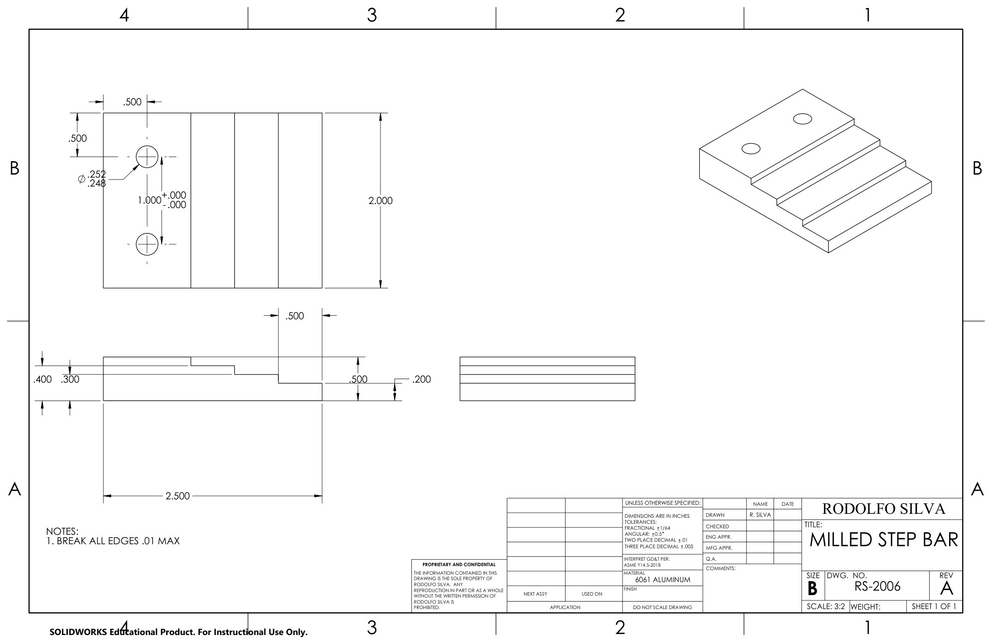
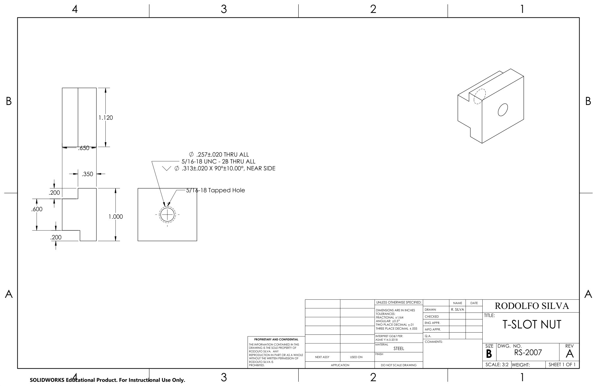
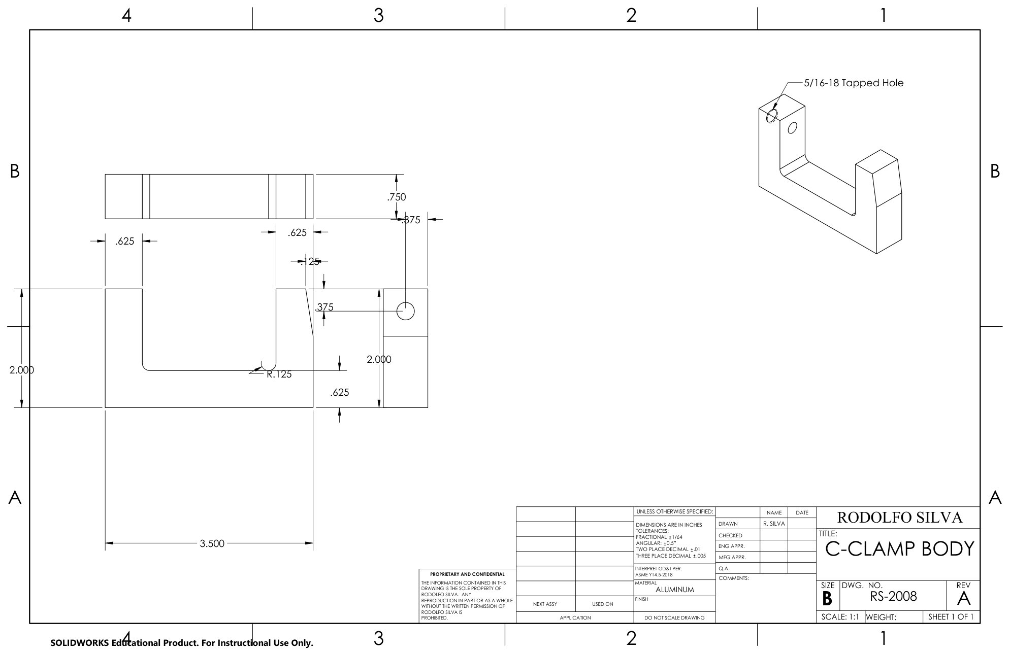
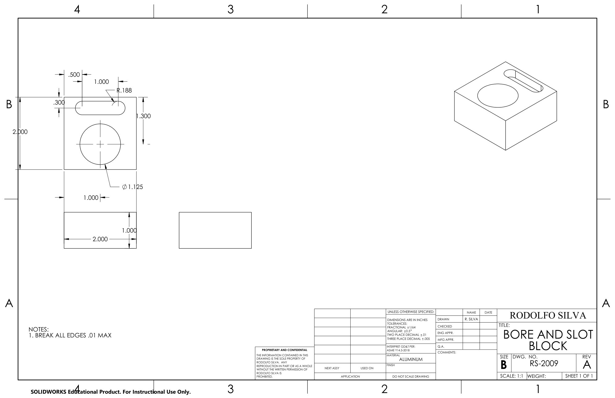
Training + personal projectIn my machining training I make these parts on manual, ProtoTRAK and Haas CNC machines. At home I program the same parts in SolidWorks CAM, to plan each one as a CNC job: setups, tools and operations.
Making a part by hand, every choice shows: how to hold it, which surface to cut first, where a tolerance can be lost when you flip it.
Production runs on CNC. A manufacturing engineer needs to judge a CAM plan, its setups, tools and operations, as well as the drawing.
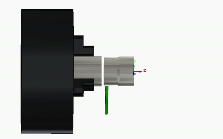
For each training print I build the SolidWorks model, set the stock and workholding in SolidWorks CAM, pick tools and operations, simulate the toolpaths and post the G-code.
Every training part is modeled. Five have CAM programs and toolpath simulations, and my programs have run on the school's Haas CNC machines.

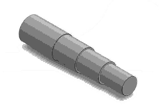
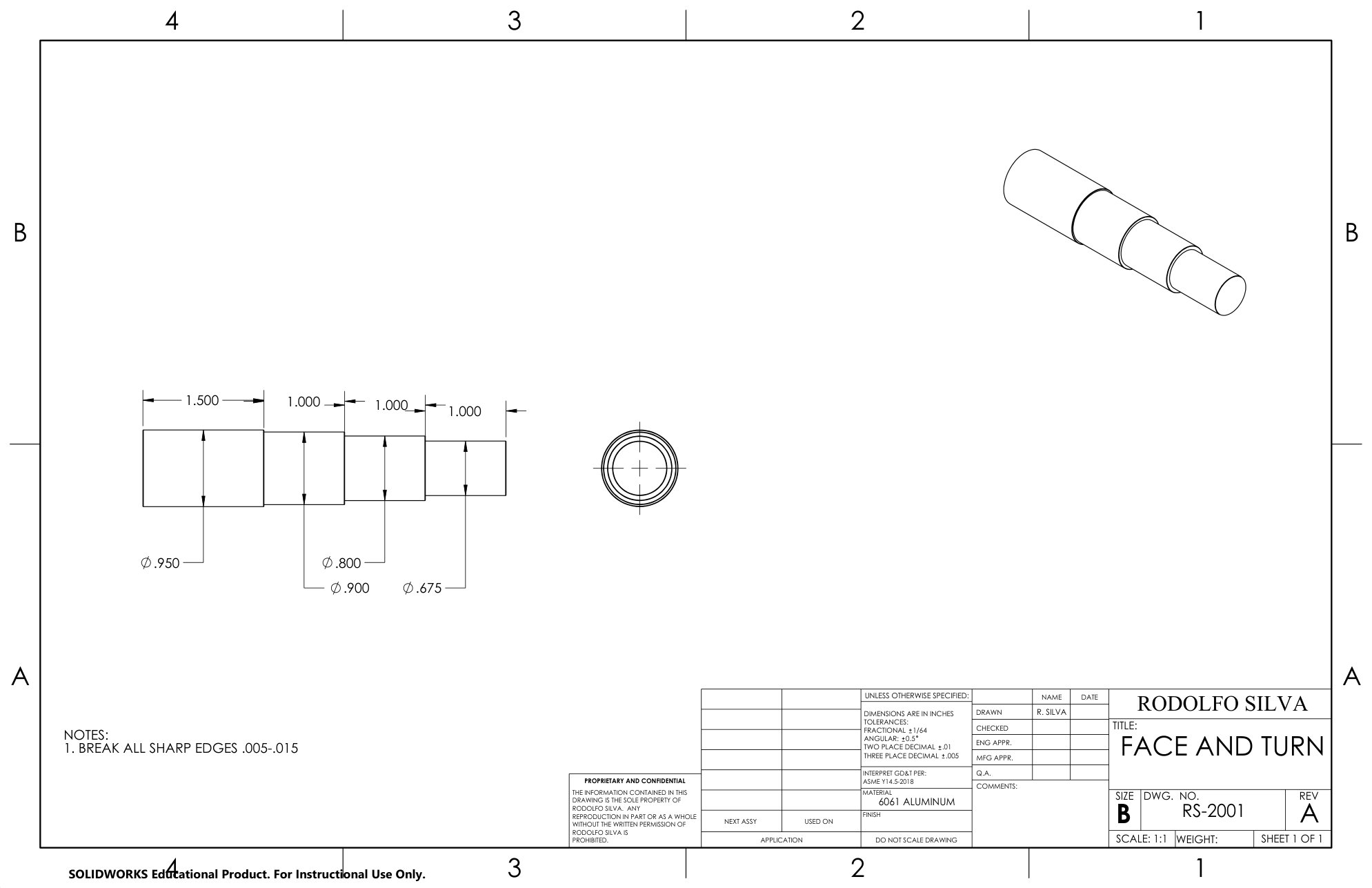
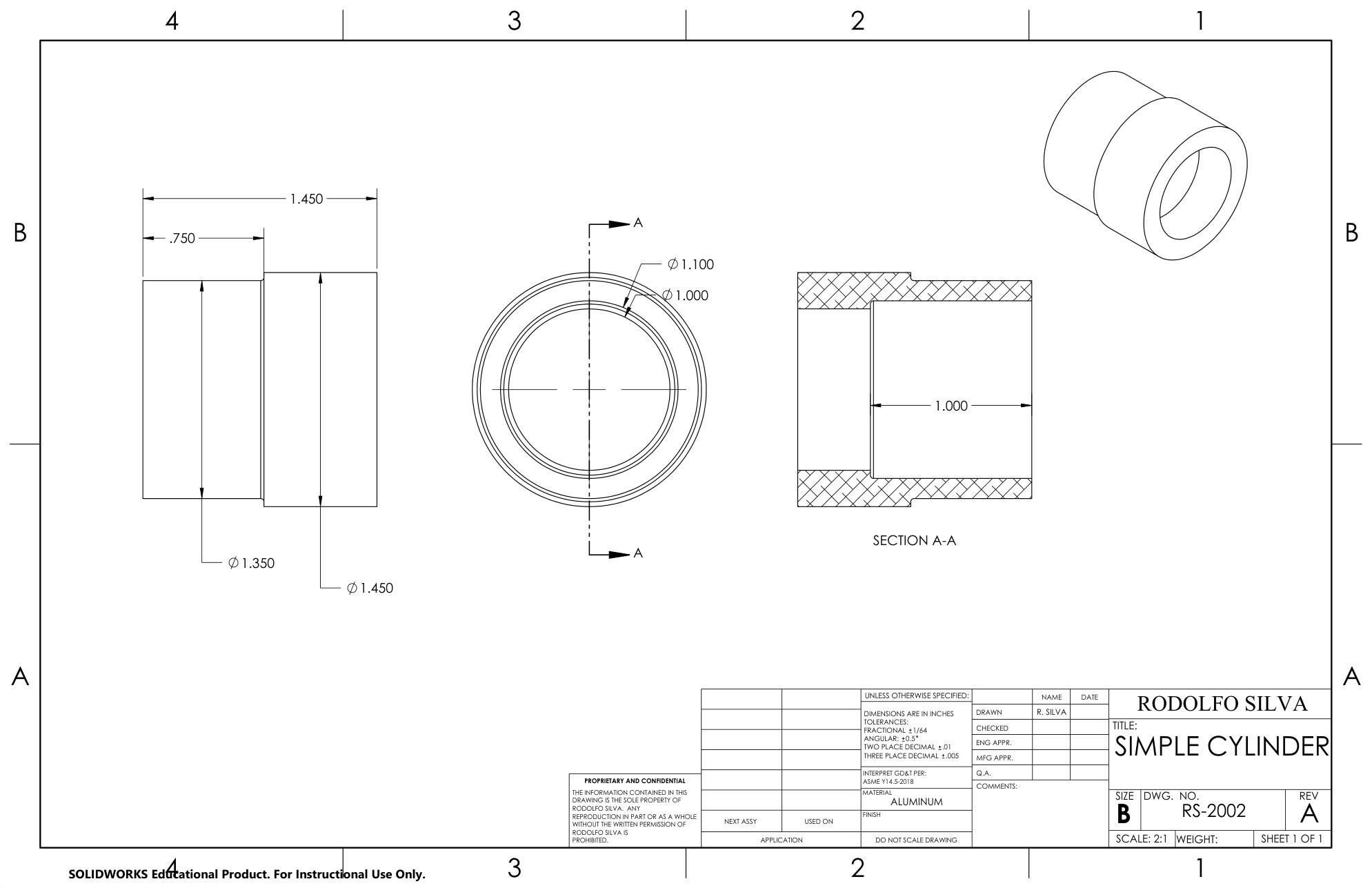
Four stepped diameters, Ø0.950 to Ø0.675. Program: face, rough and finish turn, cut-off, with 80° and 55° inserts.
CAM programmed simulated
Turned cylinder, first lathe exercise.
simulated
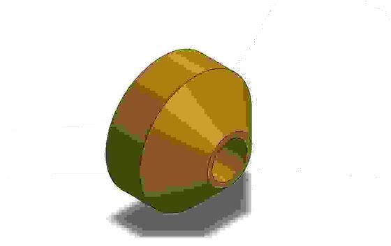
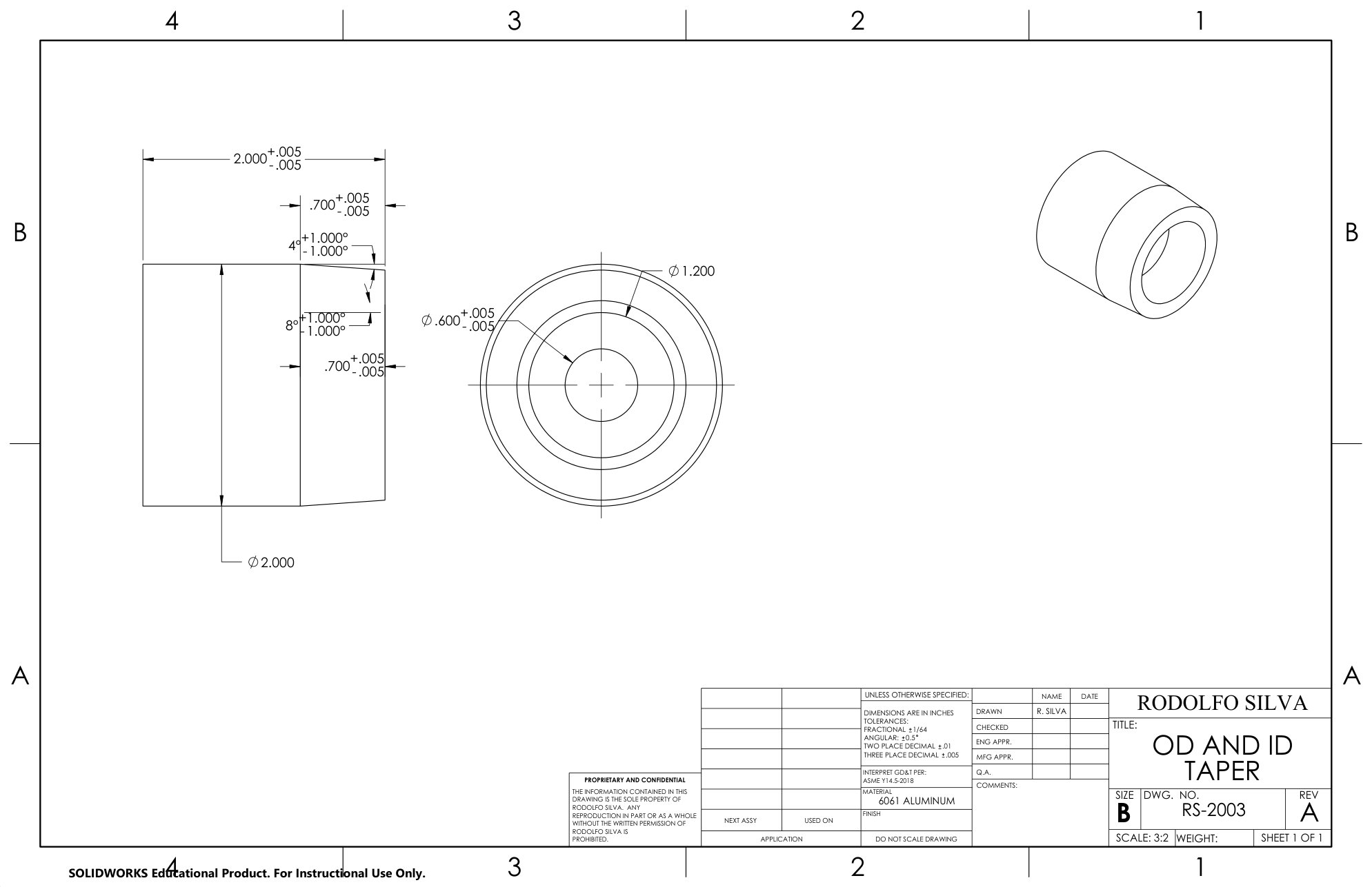
Outside and inside tapers with a Ø1.200 bore held concentric to the OD. Program: 11 operations, from facing through drilling, boring and cut-off.
CAM programmed
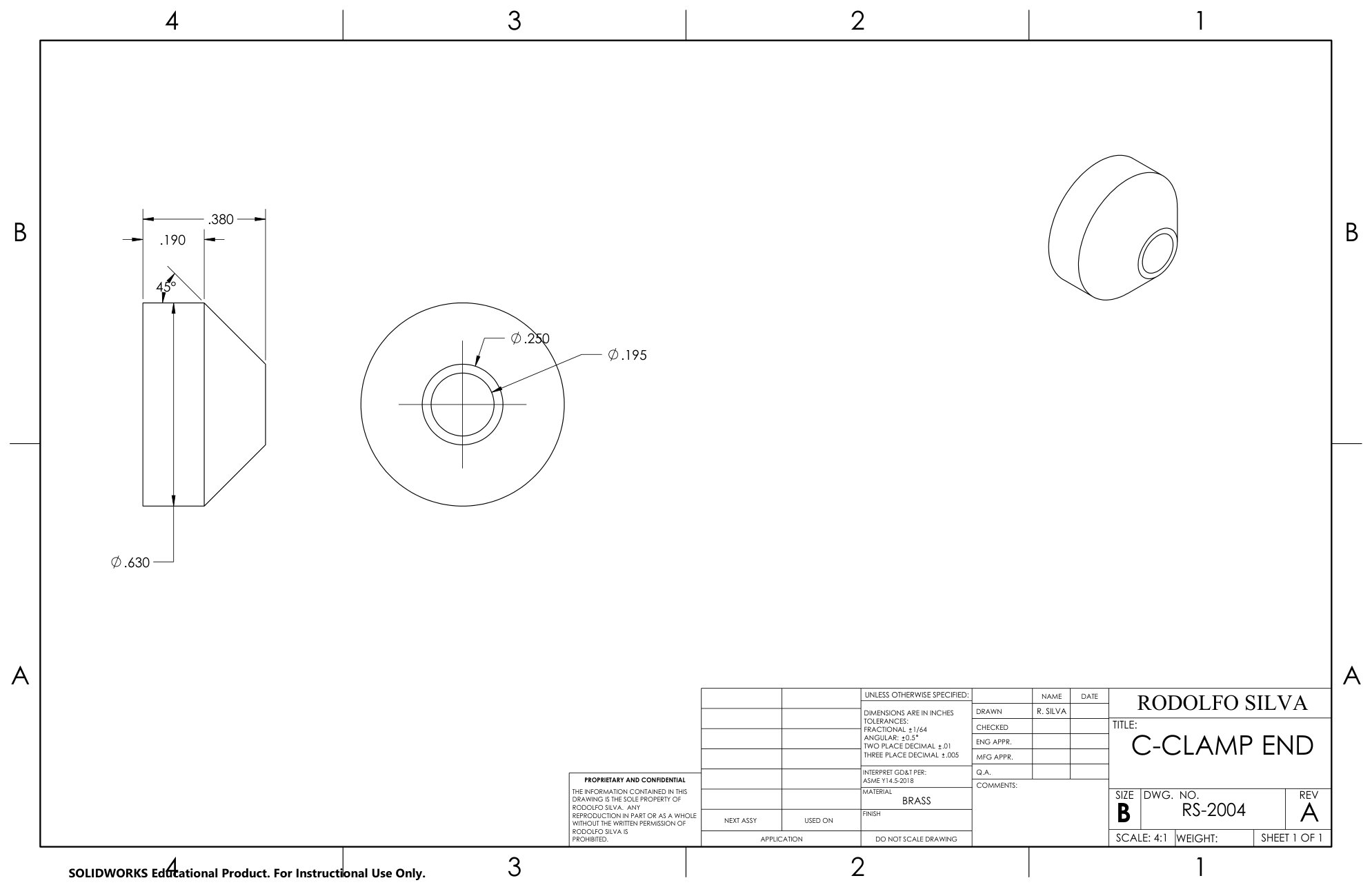
Turned end for the C-clamp assembly.
modeled
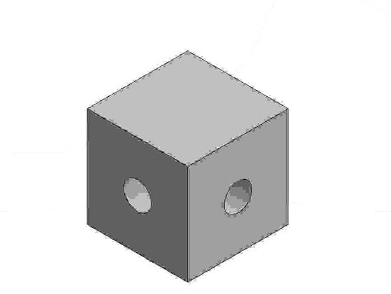
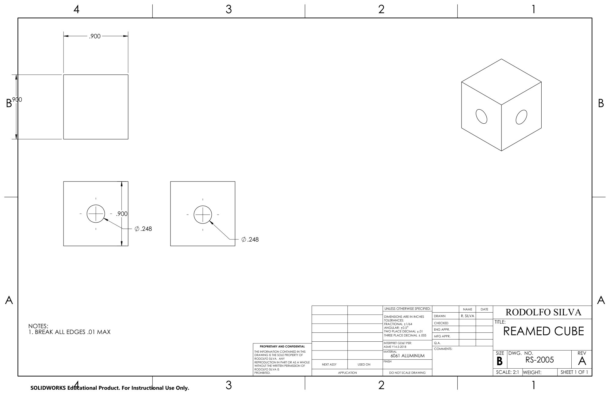
0.900 in cube with Ø0.248 reamed holes on two faces. Two setups: end mill, spot drill, drill, reamer.
CAM programmed simulated
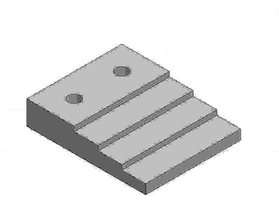
Stepped bar with a reamed Ø0.250 hole. Two setups: end mill, center drill, drill, reamer.
CAM programmed
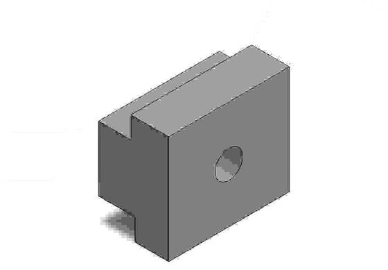
Milled T-profile with a tapped hole.
modeled
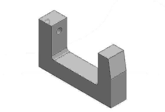
3.50 × 2.00 in U-body with a 7/16-14 tapped hole held square to datum B.
modeled
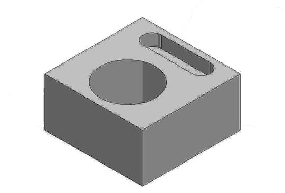
Block with a bored hole and a milled slot.
modeledThe order of cuts that works on a manual mill isn't always the best order for a CNC program.
Where the drawing puts its datums decides how the part is held and when it gets flipped.
Calipers, micrometers, height gauges and indicators on every part, against GD&T callouts.
Programming each part makes me plan it as a production job: fewest setups, the right tools and safe toolpaths.
Work samples / Medical stent DOE
Graduate · manufacturer dataUsing a medical manufacturer's test data, I ran a designed experiment on a stent's barb geometry and found settings that meet all three strength targets at once, then built the full DMAIC project around it.
Barb depth, barb length, overlap and orientation all affect tensile strength, compression and barb retention, and they pull in different directions.
Barb retention keeps the stent from moving after it's placed. It was the hardest of the three to hit.
Defined retention as the critical requirement, planned the measurement, ran the factorial and checked each model, optimized all three responses together, then wrote the FMEA and control plan.
Two settings meet all three targets. Predicted retention 0.327 against a 0.250 target.
| Response | Model fit (R² / predicted) | Target | Predicted at best setting | Type |
|---|---|---|---|---|
| Tensile | 98.3% / 93.0% | 1.250 | 1.445 | predicted |
| Compression | 65.4% / weak | 0.075 | 0.0875 | predicted |
| Barb retention | 96.4% / 88.3% | 0.250 | 0.327 | predicted |
Depth helps retention and hurts tensile. The DOE put a number on that instead of an argument.
The compression model wasn't significant (p = 0.079). It stayed in, flagged, instead of being trusted.
Tuning one response at a time would have broken another. Optimizing all three at once found settings that satisfy every target.
Work samples / Production flow and lead time
Graduate case · modeledA line that couldn't reach 28 units a day without overtime, and a 9-week lead time. Takt math, a variation study and a batch-size change fixed both on paper without new equipment.
Takt is 1,029 s. Electronics took 1,440 s (40% over) and one assembly station 1,152 s. Every other station had spare time.
The line needed overtime every day, and inventory made total lead time about 9 weeks.
Moved work off the two slow stations. In machining, compared a faster process against a steadier one. In molding, cut batches from weekly to daily.
Balanced labor content is 999 s per unit, under takt with the same 10 people. Lead time drops from ~9 to ~3.2 weeks.
| Area | Before | After | Type |
|---|---|---|---|
| Assembly | Overtime to reach 28/day | 28/day, no overtime | calculated |
| Machining buffer (cut variation 50%) | 2 weeks | 1 week | projected |
| Molding (weekly → daily batches) | 7.0 weeks | 2.2 weeks | calculated |
| Total lead time | ~9 weeks | ~3.2 weeks | projected |
In machining, halving the variation did more for lead time than cutting the average time by 10%.
More setups cost a little scrap but freed five weeks of inventory.
The line met demand with the same 10 people by moving work between stations, not by adding equipment.
Work samples / Steel shelf bracket FEA
Graduate projectChecking a formed steel shelf bracket against a safety factor of 2, I found a stress peak that was a modeling error, not a real stress. Fixing the supports gave a result that matched hand calculations within 0.9%.
Across four meshes, deflection changed less than 0.25%, but the peak stress at the fixed edge climbed from 11,461 to 19,350 psi.
Taken at face value, that peak would have rejected a bracket that is actually safe.
Traced it to a rigid support edge (a singularity). Replaced it with screw patches and wall bearing, then checked equilibrium, three meshes and beam theory.
The real governing stress is at the inner bend: 9,233 psi, within 0.9% of curved-beam theory.
| Check | Model | Reference |
|---|---|---|
| Vertical equilibrium | 50.0000 lbf | 50 lbf applied |
| Bend stress, 3 meshes | 9,220–9,287 psi | within 0.7% |
| Bend vs curved-beam theory | 9,233 psi | 9,317 psi (−0.9%) |
| Leg stress below bend | 7,561 psi | 7,500 psi (+0.8%) |
| Shelf-tip deflection | 0.0265 in | 0.025–0.027 in |
| What | Value | How I know | Type |
|---|---|---|---|
| Governing stress (inner bend) | 9,233 psi | Three meshes and curved-beam theory | calculated |
| Factor of safety | 3.9 | Yield 36,259 psi ÷ governing stress (target 2) | calculated |
| Material that could come out | Lower leg and shelf tip | Topology study, 70% volume limit | simulated |
A stress that grows with every refinement is a warning about the model, not the part.
A reaction-force review caught a support placed in the wrong spot.
Each model result was checked against an independent reference: equilibrium, a mesh study and hand calculations.
Work samples / CAD models and drawings
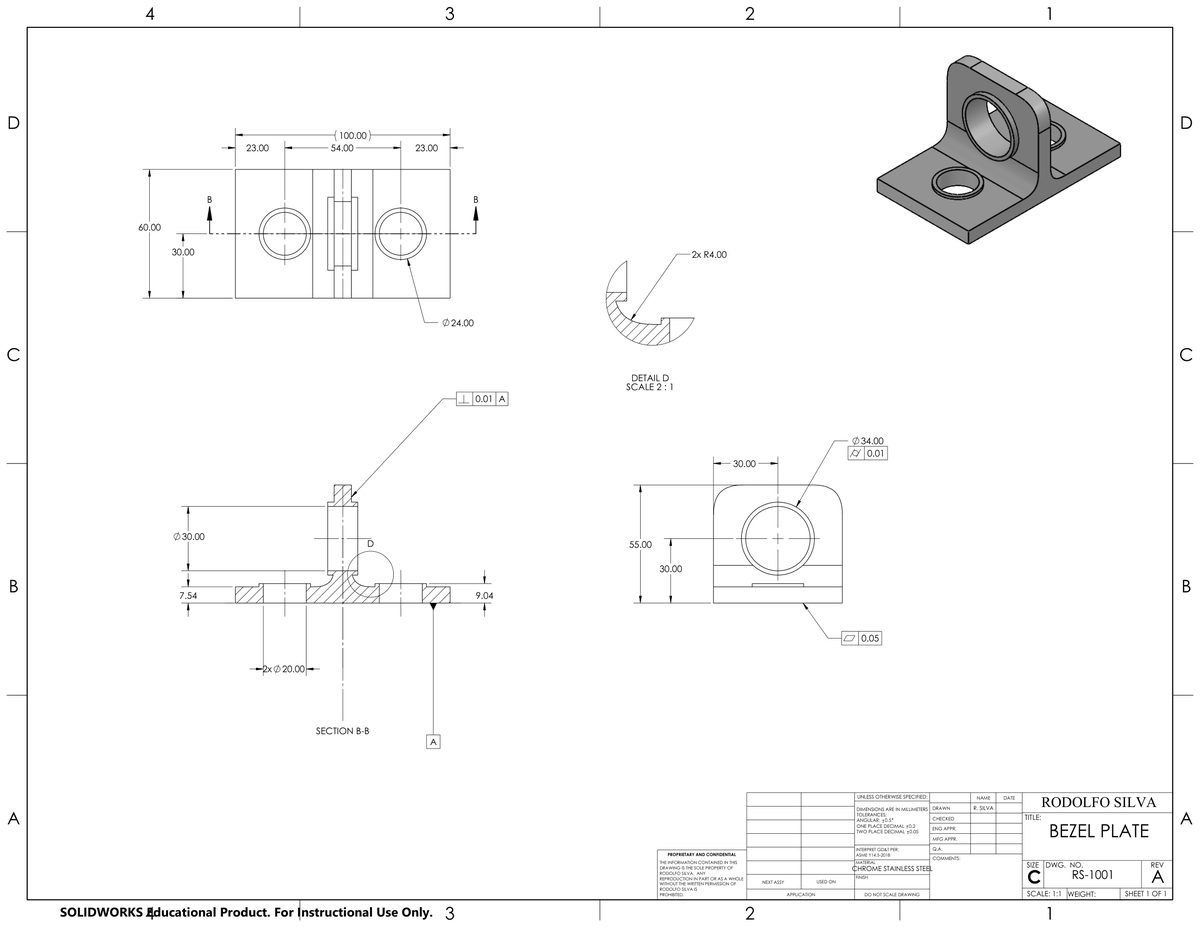
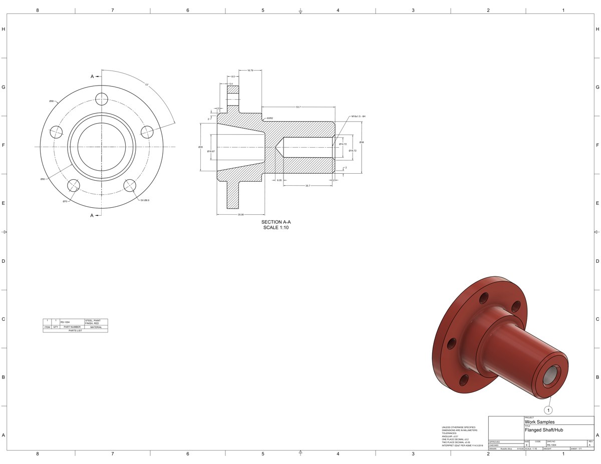
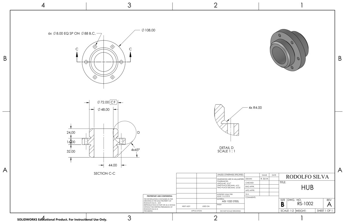
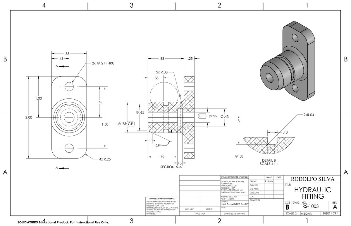
CourseworkFour parts taken from a 3D model to a dimensioned drawing a shop could quote and make from: section views, detail views, tolerances and geometric controls.


Work samples / Product launch schedule
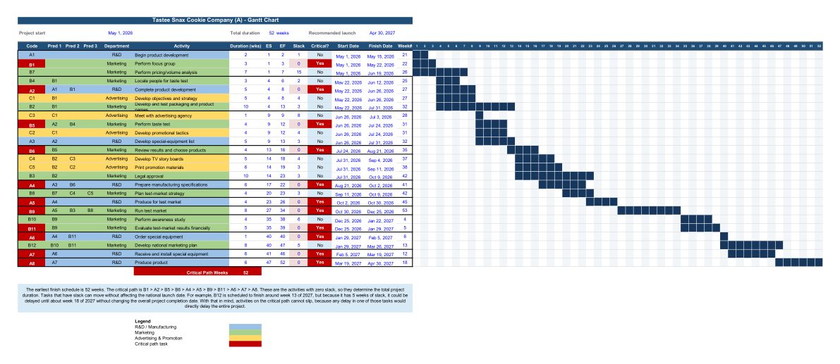
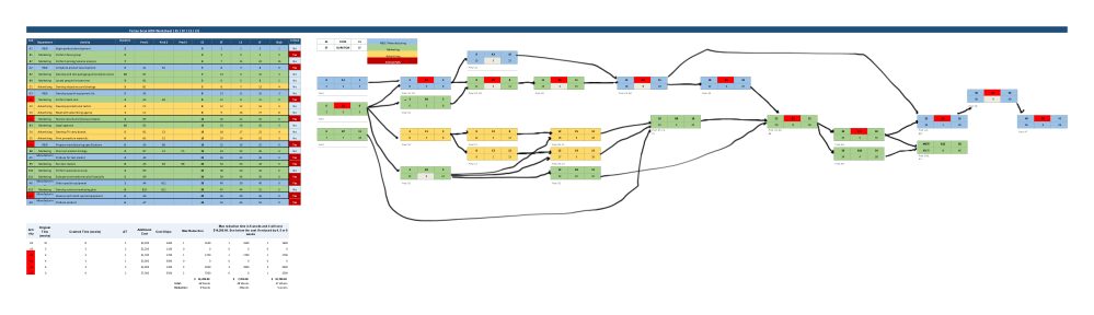
CourseworkA new-product launch with 25 activities across R&D, marketing and advertising. I built the network and Gantt chart, found the 11 activities that set the launch date, and priced the cheapest way to finish sooner.
Three departments, many hand-offs, and a launch date nobody could defend.
Only some tasks decide the date. Managers need to know which ones to protect.
Forward and backward pass for every activity, slack for each, then cost per week saved for the activities that could be shortened.
11 zero-slack activities set the date. Cutting 4 weeks costs $7,200; the full 6 weeks costs $14,200.


| Option | Duration | Added cost | Type |
|---|---|---|---|
| Earliest-finish schedule | 52 weeks | — | calculated |
| Crash 4 weeks | 48 weeks | $7,200 | calculated |
| Crash 5 weeks | 47 weeks | $10,700 | calculated |
| Crash 6 weeks (maximum) | 46 weeks | $14,200 | calculated |
Skills & evidence
Each skill on my résumé, linked to the projects and jobs where I used it.
Core skills from my résumé
Datums decide how I hold and flip a part; my drawings carry tolerances, the GD&T standard and ASME Y14.5 practice.
ProjectsMachined parts and CAM · CAD drawings · Bracket FEAJobsAeroRepair · HPM MachiningMoved final-inspection catches back to the operation that caused them; rework trends by type and station.
ProjectsAircraft shaft reliability · Defect trackingJobsEagle Woodworking · Magellan AerospaceGrind variation behind shaft rejects; hose routing behind field ruptures; a rigid support behind a false FEA stress.
ProjectsAircraft shaft reliability · Forestry hose FMEA · Bracket FEAJobsJohn Deere · Magellan AerospaceEvery rework logged and followed until it is closed; gauging, a reaction plan and SOPs at the grinder; a control for each top hose risk.
ProjectsDefect tracking · Aircraft shaft reliability · Forestry hose FMEAJobsEagle Woodworking · John Deere · AeroRepair · HPM MachiningScored failure modes by severity, occurrence and detection, with a control for each top risk (ID grind, RPN 640).
ProjectsAircraft shaft reliability · Forestry hose FMEA · Stent DOE and Six SigmaJobsJohn Deere · Magellan AerospacePlanned the measurement before the experiment; moved measurement to the grinder with in-process air gauging.
ProjectsStent DOE and Six Sigma · Aircraft shaft reliabilityA drift reaction plan at the grinder and a control plan to hold the stent settings.
ProjectsAircraft shaft reliability · Stent DOE and Six SigmaCapability study showed variation, not the spec, drove rejects: Cp 0.50 to 1.10. Capability baseline for the stent.
ProjectsAircraft shaft reliability · Stent DOE and Six SigmaJobsMagellan AerospaceCalipers, micrometers, height gauges and indicators against GD&T callouts; precision tolerance checks and final inspection.
ProjectsMachined parts and CAM · Aircraft shaft reliabilityJobsAeroRepair · HPM MachiningCore skills from my résumé
Lost time ranked by cause; failures ranked by source; rework and waste on a live dashboard with trend reports.
ProjectsProduction line flow, Fig. 4 · Defect tracking · Aircraft shaft reliabilityJobsEagle Woodworking2⁴ full factorial with center points, ANOVA and multi-response optimization.
ProjectsStent DOE and Six SigmaValue stream map, painted floor zones and break calls; a full DMAIC project; 5S at the bench.
ProjectsProduction line flow, Fig. 6 · Break-time standardization · Line balancing and lead time · Stent DOE and Six SigmaJobsEagle Woodworking · AeroRepairDaily output +24%; first-pass yield 84.4% to 97.75%; break-related loss cut in half.
ProjectsProduction line flow · Aircraft shaft reliability · Break-time standardization · Defect tracking · Line balancing and lead timeJobsEagle Woodworking · Magellan AerospaceSolidWorks and Fusion 360 models taken to released drawings; nine training parts modeled.
ProjectsCAD drawings · Machined parts and CAM · Bracket FEAFrom my résumé
Factorial design, ANOVA, regression and desirability optimization.
ProjectsStent DOE and Six SigmaQueue counts, loss log, Little's Law targets and a dashboard that updates itself; crash analysis for a launch schedule.
ProjectsProduction line flow, Fig. 3 · Launch scheduleJobsEagle WoodworkingPart models, SolidWorks CAM programs with simulated toolpaths, and Rev A drawings.
ProjectsMachined parts and CAM · CAD drawings · Bracket FEADiscrete-event model of a 17-step line with cure buffers and real starting queues.
ProjectsProduction line flow, Fig. 5JobsEagle WoodworkingUsed in MECH 5120 Applied FEA, a UMass Lowell graduate course, starting with a beam study. The course's final project, the steel bracket, was solved in Abaqus.
ProjectsBracket FEACourseMECH 5120 Applied FEA, Graduate Certificate in Design and ManufacturingMapped a 17-step line from order to shipping, with every queue and wait.
ProjectsProduction line flowJobsEagle WoodworkingTimed every station and separated real work from handling; logged lost time by cause.
ProjectsProduction line flow, Fig. 2 · Break-time standardizationJobsEagle WoodworkingFound the constraint from cycle times, confirmed it in simulation, and rebalanced labor around it.
ProjectsProduction line flow, Fig. 5 · Line balancing and lead timeJobsEagle WoodworkingSized each queue with Little's Law and separated required cure time from extra waiting.
ProjectsProduction line flow, Fig. 3 · Line balancing and lead timeJobsEagle WoodworkingParts made on Haas CNC, ProtoTRAK and manual machines, and programmed in SolidWorks CAM.
ProjectsMachined parts and CAMMesh convergence, equilibrium check and agreement with hand calculations within 0.9% (Abaqus).
ProjectsBracket FEANetwork diagram, Gantt chart, slack and crash plan for a 52-week launch.
ProjectsLaunch scheduleJobsMagellan AerospaceEach unit counted at each station from a label scan, so progress is known without walking the floor.
ProjectsDefect trackingJobsEagle WoodworkingPicture cards anyone can read at a glance; loss data taken to the team to pick the fix; SOPs and training at the grinder.
ProjectsDefect tracking · Break-time standardization · Aircraft shaft reliabilityJobsEagle Woodworking · John DeereExperience
Manufacturing and aerospace first, then the roles that taught me to run a team and keep a shop moving.
Eagle Woodworking · fully custom, made-to-order production line
Case studies: Production line flow · Defect tracking · Break-time standardization
Magellan Aerospace · AS9100 machine shop
Case study: Aircraft shaft reliability and process capability
AeroRepair Corp · FAA Part 145 repair station
HPM Machining Services · repair and machining
John Deere · forestry equipment
Case study: Forestry harvester hose FMEA
Massachusetts National Guard
Real Auto Shop
Education
From graduate engineering to hands-on machining, plus professional memberships. Click a certificate or diploma to open it. Identity numbers are removed.
UMass Lowell · in progress
UCAM, Brazil · 600-hour graduate program
UMass Lowell · design of experiments, quality engineering, design for reliability, FEA, plastics product design
UNILESTE, Brazil · evaluated as equivalent to a U.S. bachelor's in mechanical engineering
Essex North Shore Agricultural & Technical School, Danvers, MA · 400 hours, hands-on: Haas Mini Mill, TM-1, VF-2, TL-1 and TL lathe; ProtoTRAK mills and lathes; manual engine lathes; G-code, setup and tooling; precision measurement; blueprint reading and GD&T
National Institute for Metalworking Skills
North Shore Community College, Danvers, MA
Occupational Safety and Health Administration
Geomiq Academy · Mastering 3D GD&T: symbols, datums and tolerances for manufacturing, inspection and quality control
Coursera project
DMAIC, statistical process control, design for Six Sigma
Project planning, scheduling and cost control
Student member
Member
Résumé
Email me and I'll send the current version of my résumé, matched to the role if you tell me which one.
You can also message me on LinkedIn.
rodolfo [at] rodolfosilva [dot] engineer
The button opens your email program with the subject filled in.
Four stepped diameters from Ø0.950 to Ø0.675 in, sharp edges broken .005–.015.

O0001 (SPEEDS CHECKED FOR 6061 ALUMINUM - MAX 1800 RPM - HAAS TL LATHE) N1 (CNMG 431 80DEG SQR HOLDER) N2 T0101 N3 B90. G50 S1800 N4 G00 G96 S1800 M03 N5 ( Face Rough1 ) N6 G54 G00 Z.2571 M08 N7 X1.2141 N8 G99 G01 X1. Z.15 F.0161 N9 X-.0314 N10 X-.0455 Z.1571 N11 G00 Z.2571 N12 X1.0141 N13 Z.1171 N14 G01 X1. Z.11 N15 X-.0314 N16 X-.0455 Z.1171 N17 G00 Z.2171 N18 X1.0141 N19 Z.0171 N20 G01 X1. Z.01 N21 X-.0314 N22 X-.0455 Z.0171 N23 G00 Z.3343 N24 X20. Z5. M09 N25 M01 N26 (DNMG 431 55DEG SQR HOLDER) N27 T0303 N28 B90. G50 S1800 N29 G00 G96 S1800 M03 N30 ( Face Finish1 ) N31 G54 G00 Z.1071 M08 N32 X1.1827 N33 G01 X.9686 Z0 F.0161 N34 X-.0314 N35 X-.0455 Z.0071 N36 G00 X20. Z5. M09 N37 M01 N38 (CNMG 431 80DEG SQR HOLDER) N39 T0101 N40 B90. G50 S1800 N41 G00 G96 S1800 M03 N42 ( Turn Rough1 ) N43 G54 G00 Z.1071 M08 N44 X1.0141 N45 G01 X.8 Z0 F.0161 N46 Z-.969 N47 G03 X.87 Z-1.0207 R.0557 N48 G01 Z-1.9653 N49 G03 X.97 Z-2.0207 R.0557 N50 G01 Z-2.9742 N51 G03 X1. Z-2.9889 R.0557 N52 G01 X1.0197 Z-2.9906 N53 X1.0497 N54 G00 X1.2197 N55 Z.009 N56 X.7457 N57 G01 X.7371 Z0 N58 X.7386 Z-.0021 N59 G03 X.745 Z-.0207 R.0557 N60 G01 Z-.965 N61 X.7586 N62 G03 X.8 Z-.969 R.0557 N63 G01 X.8184 Z-.9651 N64 Z-.93 N65 G00 Z-.0014 N66 X.7001 N67 G01 X.6915 Z-.0105 N68 G03 X.695 Z-.0207 R.0307 N69 G01 Z-.99 N70 X.7586 N71 G03 X.82 Z-1.0207 R.0307 N72 G01 Z-1.99 N73 X.8586 N74 G03 X.92 Z-2.0207 R.0307 N75 G01 Z-2.9905 N76 G03 X.97 Z-3.0207 R.0307 N77 G01 Z-4.5107 N78 G03 X.9695 Z-4.5144 R.0307 N79 G01 X.9692 Z-4.5157 N80 X.9815 Z-4.5236 N81 G00 X1.1815 N82 X20. Z5. M09 N83 M01 N84 (DNMG 431 55DEG SQR HOLDER) N85 T0303 N86 B90. G50 S1800 N87 G00 G96 S1800 M03 N88 ( Turn Finish1 ) N89 G54 G00 Z.1071 M08 N90 X.8195 N91 G01 X.6195 Z.0071 F.0161 N92 X.6336 Z0 N93 G03 X.675 Z-.0207 R.0207 N94 G01 Z-1. N95 X.7586 N96 G03 X.8 Z-1.0207 R.0207 N97 G01 Z-2. N98 X.8586 N99 G03 X.9 Z-2.0207 R.0207 N100 G01 Z-3. N101 X.9086 N102 G03 X.95 Z-3.0207 R.0207 N103 G01 Z-4.5107 N104 G03 X.9478 Z-4.5174 R.0207 N105 G01 X.9566 Z-4.5263 N106 X.9686 N107 G00 X1.1566 N108 X20. Z5. M09 N109 M01 N110 (0.118W CUT-OFF BLADE) N111 T1010 N112 B90. G50 S1800 N113 G00 G96 S1037 M03 N114 ( Cut Off1 ) N115 G54 G00 Z-4.518 M08 N116 X1.356 N117 G01 Z-4.618 F.0036 N118 X.756 N119 G00 X.956 N120 G01 X.556 N121 G00 X.756 N122 G01 X.356 N123 G00 X.556 N124 G01 X.156 N125 G00 X.356 N126 G01 X-.016 N127 G00 X1.34 N128 X20. Z5. M09 N129 M30
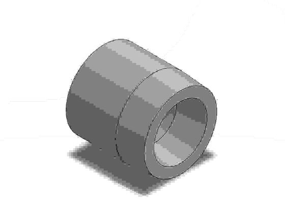
A turned cylinder with a drilled and bored inside diameter: the first lathe exercise.

Outside and inside tapers with a Ø1.200 in bore held concentric to the outside diameter.

% O0001 (SPEEDS CHECKED FOR 6061 ALUMINUM - MAX 1800 RPM - HAAS TL LATHE) G00 G18 G40 G80 G97 G99 N1 ( Face Rough1 ) G54 T0101 (CNMG 431 80DEG SQR HOLDER) G97 S1000 M03 G99 G18 G00 Z.1171 M08 G50 S1800 G96 S1800 X2.3141 G01 X2.1 Z.01 F.0161 X-.0314 X-.0455 Z.0171 G00 Z.1343 X20. Z5. M09 M01 N2 ( Face Finish1 ) G54 T0303 (DNMG 431 55DEG SQR HOLDER) G97 S1000 M03 G99 G18 G00 Z.1071 M08 G50 S1800 G96 S1800 X2.2827 G01 X2.0686 Z0 F.0161 X-.0314 X-.0455 Z.0071 G00 X20. Z5. M09 M01 N3 ( Turn Rough1 ) G54 T0101 (CNMG 431 80DEG SQR HOLDER) G97 S1000 M03 G99 G18 G00 Z.1071 M08 G50 S1800 G96 S1800 X2.1922 G01 X1.978 Z0 F.0161 Z-.0563 X2.0698 Z-.7122 G03 X2.07 Z-.7157 R.0507 G01 Z-1.9907 X2.1 X2.1141 Z-1.9836 X2.1441 G00 X2.3141 Z.0075 X1.9833 G01 X1.9702 Z0 X1.978 Z-.0563 X1.9931 Z-.0629 G00 Z.0086 X1.933 G01 X1.9199 Z.0011 X2.0199 Z-.7139 G03 X2.02 Z-.7157 R.0257 G01 Z-2.0157 X2.0686 X2.0827 Z-2.0086 G00 X2.2827 X20. Z5. M09 M01 N4 ( Turn Finish1 ) G54 T0303 (DNMG 431 55DEG SQR HOLDER) G97 S1000 M03 G99 G18 G00 Z.0929 M08 G50 S1800 G96 S1800 X2.1151 G01 X1.9151 Z-.0071 F.0161 X1.902 Z-.0146 X1.9999 Z-.7146 G03 X2. Z-.7157 R.0157 G01 Z-2.0168 X2.0141 Z-2.0238 X2.0686 G00 X2.2141 X20. Z5. M09 M01 N5 ( Center Drill3 ) G54 T0505 (#3 60DEG HSS CENTERDRILL) G97 S1800 M03 G98 G18 G00 Z.1 M08 X0 G74 Z-.1 F4.3204 M01 N6 ( Drill3 ) G54 T0202 (19/32 SCREW MACH DRILL) G97 S1600 M03 G99 G18 G00 Z.1774 Z.0774 G01 Z-2. F.0053 G00 Z.0774 X20. Z5. M09 M01 N7 ( Center Drill4 ) G54 T0505 (#3 60DEG HSS CENTERDRILL) G97 S1800 M03 G98 G18 G00 X0 M08 G74 Z-.1 F4.3204 M01 N8 ( Drill4 ) G54 T1111 (1/2 SCREW MACH DRILL) G97 S1800 M03 G98 G18 G00 Z.1 G01 Z-.1 F9.0013 G00 Z.1 Z0 G01 Z-.2 G00 Z.1 Z-.1 G01 Z-.3 G00 Z.1 Z-.2 G01 Z-.4 G00 Z.1 Z-.3 G01 Z-.5 G00 Z.1 Z-.4 G01 Z-.6 G00 Z.1 Z-.5 G01 Z-.7 G00 Z.1 Z-.6 G01 Z-.8 G00 Z.1 Z-.7 G01 Z-.9 G00 Z.1 Z-.8 G01 Z-1. G00 Z.1 Z-.9 G01 Z-1.1 G00 Z.1 Z-1. G01 Z-1.2 G00 Z.1 Z-1.1 G01 Z-1.3 G00 Z.1 Z-1.2 G01 Z-1.4 G00 Z.1 Z-1.3 G01 Z-1.5 G00 Z.1 Z-1.4 G01 Z-1.6 G00 Z.1 Z-1.5 G01 Z-1.7 G00 Z.1 Z-1.6 G01 Z-1.8 G00 Z.1 Z-1.7 G01 Z-1.9 G00 Z.1 Z-1.8 G01 Z-2. G00 Z.1 X20. Z5. M09 M01 N9 ( Bore Rough5 ) G54 T0404 (CNMG 431 80DEG BORE BAR) G97 S1000 M03 G99 G18 G00 X.5797 M08 G50 S1800 G96 S1800 Z.1071 G01 X.7938 Z0 F.0161 Z-1.4008 X.6314 G02 X.5938 Z-1.4022 R.1257 G01 X.5777 Z-1.3962 G00 X.3777 Z.0071 X.9721 G01 X.9862 Z0 Z-.6847 X.9824 Z-.6982 G02 X.98 Z-.7157 R.1257 G01 Z-1.4008 X.7938 X.7797 Z-1.3937 X.7497 G00 X.5797 Z.008 X1.1667 G01 X1.1787 Z0 X.9862 Z-.6847 X.9703 Z-.6907 G00 Z.01 X1.3692 G01 X1.3812 Z.002 X1.1805 Z-.7121 G02 X1.18 Z-.7157 R.0257 G01 Z-1.5008 X.6314 G02 X.6155 Z-1.502 R.0257 G01 X.5976 Z-1.4975 G00 X.3145 Z-1.8728 X.5659 G01 X.58 Z-1.8799 Z-2.0157 X.0314 X.0173 Z-2.0086 G00 X-.1827 Z-2.0032 X-.3827 Z.1 X20. Z5. M09 M01 N10 ( Bore Finish1 ) G54 T0606 (DNMG 431 55DEG BORE BAR) G97 S1000 M03 G99 G18 G00 Z.0945 M08 G50 S1800 G96 S1800 X1.185 G01 X1.385 Z-.0055 F.0161 X1.3971 Z-.0135 X1.2003 Z-.7135 G02 X1.2 Z-.7157 R.0157 G01 Z-1.5108 X.6314 G02 X.6 Z-1.5265 R.0157 G01 Z-2.0168 X.5859 Z-2.0238 X.3859 G00 Z.1 X20. Z5. M09 M01 N11 ( Cut Off1 ) G54 T1010 (0.118W CUT-OFF BLADE) G97 S1000 M03 G99 G18 G00 Z-2.018 M08 G50 S1800 G96 S1037 X2.416 G01 Z-2.118 F.0036 X1.816 G00 X2.016 G01 X1.616 G00 X1.816 G01 X1.416 G00 X1.616 G01 X1.216 G00 X1.416 G01 X1.016 G00 X1.216 G01 X.816 G00 X1.016 G01 X.616 G00 X.816 G01 X.584 G00 X2.4 X20. Z5. M09 M01 M05 / M99 M30 %
The turned end of the C-clamp assembly: a chamfered head on a stepped shank that fits the clamp screw.

A 0.900 in cube with Ø0.248 in reamed holes on two faces.

% O00001 (SPEEDS CHECKED FOR 6061 ALUMINUM - MAX 4000 RPM - TM-1 / MINI MILL / VF-2) N5 G20 G17 G40 G80 G90 N10 T01 M06 (3/4 EM CRB 2FL 1-1/2 LOC) N15 G54 G90 G94 N20 S4000 M03 N25 G00 G90 X.4125 Y.4125 N30 G43 H01 Z.1 M08 N35 G01 Z-.04 F6.0123 N40 X.5875 F24.0491 N45 Y.5875 N50 X.4125 N55 Y.4125 N60 X.1125 Y.1125 N65 X.8875 N70 Y.8875 N75 X.1125 N80 Y.1125 N85 X-.1875 Y-.1875 N90 X1.1875 N95 Y1.1875 N100 X-.1875 N105 Y-.1875 N110 G00 Z.1 N115 G90 G54 X.4125 Y.4125 N120 Z.06 N125 G01 Z-.05 F6.0123 N130 X.5875 F24.0491 N135 Y.5875 N140 X.4125 N145 Y.4125 N150 X.1125 Y.1125 N155 X.8875 N160 Y.8875 N165 X.1125 N170 Y.1125 N175 X-.1875 Y-.1875 N180 X1.1875 N185 Y1.1875 N190 X-.1875 N195 Y-.1875 N200 G00 Z.1 N205 Z1. N210 S3677 N215 G90 G54 X1.6227 Y.8663 N220 Z.1 N225 G01 Z-.425 F4.0448 N230 G90 G41 X1.347 Y.5905 D01 F12.1345 N235 G03 X1.325 Y.5375 I.053 J-.053 N240 G01 Y-.325 F16.1793 N245 X-.325 N250 Y1.325 N255 X1.325 N260 Y.4625 N265 G03 X1.347 Y.4095 I.075 J0 N270 G40 G01 X1.6227 Y.1337 N275 G00 Z.1 N280 G90 G54 X1.6227 Y.8663 N285 Z-.325 N290 G01 Z-.715 F4.0448 N295 G90 G41 X1.347 Y.5905 D01 F12.1345 N300 G03 X1.325 Y.5375 I.053 J-.053 N305 G01 Y-.325 F16.1793 N310 X-.325 N315 Y1.325 N320 X1.325 N325 Y.4625 N330 G03 X1.347 Y.4095 I.075 J0 N335 G40 G01 X1.6227 Y.1337 N340 G00 Z.1 N345 G90 G54 X1.6227 Y.8663 N350 Z-.615 N355 G01 Z-1.005 F4.0448 N360 G90 G41 X1.347 Y.5905 D01 F12.1345 N365 G03 X1.325 Y.5375 I.053 J-.053 N370 G01 Y-.325 F16.1793 N375 X-.325 N380 Y1.325 N385 X1.325 N390 Y.4625 N395 G03 X1.347 Y.4095 I.075 J0 N400 G40 G01 X1.6227 Y.1337 N405 G00 Z.1 N410 Z10. M09 N415 G00 G90 G53 G49 H0 Z0 M05 N420 T03 M06 (1/4 X 90DEG CBT SPOT DRILL) N425 G54 G90 G94 N430 S4000 M03 N435 G90 X-.5 Y.5 N440 G43 H03 Z1. M08 N445 G98 G82 Z-.08 R.05 P00 F14.4275 N450 G80 Z1. M09 N455 G00 G90 G53 G49 H0 Z0 M05 N460 T04 M06 (6.1MM SCREW MACH DRILL) N465 G54 G90 G94 N470 S4000 M03 N475 G90 N480 G43 H04 Z1. M08 N485 G98 G81 Z-.9997 R.05 F14.4202 N490 G80 Z1. M09 N495 G00 G90 G53 G49 H0 Z0 M05 N500 T05 M06 (0.2480 HSS REAMER) N505 G54 G90 G94 N510 S2000 M03 N515 G90 N520 G43 H05 Z1. M08 N525 G98 G85 Z-.96 R.05 F10.4017 N530 G80 Z10. M09 N535 G00 G90 G53 G49 H0 Z0 M05 N540 T03 M06 (1/4 X 90DEG CBT SPOT DRILL) N545 G54 G90 G94 N550 S4000 M03 N555 G90 Y.5131 N560 G43 H03 Z2. M08 N565 G98 G82 Z.92 R1.05 P00 F14.4275 N570 G80 Z2. M09 N575 G00 G90 G53 G49 H0 Z0 M05 N580 T04 M06 (6.1MM SCREW MACH DRILL) N585 G54 G90 G94 N590 S4000 M03 N595 G90 N600 G43 H04 Z2. M08 N605 G98 G81 Z.0003 R1.05 F14.4202 N610 G80 Z2. M09 N615 G00 G90 G53 G49 H0 Z0 M05 N620 T05 M06 (0.2480 HSS REAMER) N625 G54 G90 G94 N630 S2000 M03 N635 G90 N640 G43 H05 Z2. M08 N645 G98 G85 Z.04 R1.05 F10.4017 N650 G80 Z2. M09 N655 G00 G90 G53 G49 H0 Z0 M05 N660 G54 X0 Y0 N665 M30 %
% O00001 (SPEEDS CHECKED FOR 6061 ALUMINUM - MAX 4000 RPM - TM-1 / MINI MILL / VF-2) N5 G20 G17 G40 G80 G90 N10 T01 M06 (3/4 EM CRB 2FL 1-1/2 LOC) N15 G55 G90 G94 N20 S4000 M03 N25 G00 G90 X-.7875 Y-.3 N30 G43 H01 Z.1 M08 N35 G01 Z-.05 F11.4286 N40 X0 F99.6 N45 X1. F132.8 N50 X1.4125 N55 G02 Y-.7 I0 J-.2 N60 G01 X1. N65 X0 N70 X-.7875 F99.6 N75 G00 Z.1 N80 G90 G55 X-.7875 Y-.3 N85 Z.05 N90 G01 Z-.148 F11.4286 N95 X0 F99.6 N100 X1. F132.8 N105 X1.4125 N110 G02 Y-.7 I0 J-.2 N115 G01 X1. N120 X0 N125 X-.7875 F99.6 N130 G00 Z.1 N135 G90 G55 X-.7875 Y-.3 N140 Z-.048 N145 G01 Z-.246 F11.4286 N150 X0 F99.6 N155 X1. F132.8 N160 X1.4125 N165 G02 Y-.7 I0 J-.2 N170 G01 X1. N175 X0 N180 X-.7875 F99.6 N185 G00 Z.1 N190 G90 G55 X-.7875 Y-.3 N195 Z-.146 N200 G01 Z-.344 F11.4286 N205 X0 F99.6 N210 X1. F132.8 N215 X1.4125 N220 G02 Y-.7 I0 J-.2 N225 G01 X1. N230 X0 N235 X-.7875 F99.6 N240 G00 Z.1 N245 G90 G55 X-.7875 Y-.3 N250 Z-.244 N255 G01 Z-.442 F11.4286 N260 X0 F99.6 N265 X1. F132.8 N270 X1.4125 N275 G02 Y-.7 I0 J-.2 N280 G01 X1. N285 X0 N290 X-.7875 F99.6 N295 G00 Z.1 N300 G90 G55 X-.7875 Y-.3 N305 Z-.342 N310 G01 Z-.54 F11.4286 N315 X0 F99.6 N320 X1. F132.8 N325 X1.4125 N330 G02 Y-.7 I0 J-.2 N335 G01 X1. N340 X0 N345 X-.7875 F99.6 N350 G00 Z.1 N355 G90 G55 X-.7875 Y-.3 N360 Z-.44 N365 G01 Z-.55 F11.4286 N370 X0 F99.6 N375 X1. F132.8 N380 X1.4125 N385 G02 Y-.7 I0 J-.2 N390 G01 X1. N395 X0 N400 X-.7875 F99.6 N405 G00 Z.1 N410 Z1. M09 N415 G00 G90 G53 G49 H0 Z0 M05 N420 G55 X0 Y0 N425 M30 %
A stepped bar with a Ø0.250 in reamed hole.

% O00001 (SPEEDS CHECKED FOR 6061 ALUMINUM - MAX 4000 RPM - TM-1 / MINI MILL / VF-2) N5 G20 G17 G40 G80 G90 N10 T04 M06 (3/4 EM CRB 2FL 1-1/2 LOC) N15 G54 G90 G94 N20 S4000 M03 N25 G00 G90 X-.8875 Y1.725 N30 G43 H04 Z.25 M08 N35 G01 Z.1 F2.3447 N40 X-.1 F99.6083 N45 X2.6 F132.811 N50 X3.0125 N55 G02 Y1.2417 I0 J-.2417 N60 G01 X2.6 N65 X-.1 N70 X-.5125 N75 G03 Y.7583 I0 J-.2417 N80 G01 X-.1 N85 X2.6 N90 X3.0125 N95 G02 Y.275 I0 J-.2417 N100 G01 X2.6 N105 X-.1 N110 X-.8875 F99.6083 N115 G00 Z.25 N120 G90 G54 X-.8875 Y1.725 N125 Z.2 N130 G01 Z.05 F2.3447 N135 X-.1 F99.6083 N140 X2.6 F132.811 N145 X3.0125 N150 G02 Y1.2417 I0 J-.2417 N155 G01 X2.6 N160 X-.1 N165 X-.5125 N170 G03 Y.7583 I0 J-.2417 N175 G01 X-.1 N180 X2.6 N185 X3.0125 N190 G02 Y.275 I0 J-.2417 N195 G01 X2.6 N200 X-.1 N205 X-.8875 F99.6083 N210 G00 Z.25 N215 G90 G54 X-.8875 Y1.725 N220 Z.15 N225 G01 Z0 F2.3447 N230 X-.1 F99.6083 N235 X2.6 F132.811 N240 X3.0125 N245 G02 Y1.2417 I0 J-.2417 N250 G01 X2.6 N255 X-.1 N260 X-.5125 N265 G03 Y.7583 I0 J-.2417 N270 G01 X-.1 N275 X2.6 N280 X3.0125 N285 G02 Y.275 I0 J-.2417 N290 G01 X2.6 N295 X-.1 N300 X-.8875 F99.6083 N305 G00 Z.25 N310 Z1.15 N315 S3677 N320 G90 G54 X1.6163 Y-.6727 N325 Z.25 N330 G01 Z-.375 F4.0448 N335 G90 G41 X1.3405 Y-.397 D04 F12.1345 N340 G03 X1.2875 Y-.375 I-.053 J-.053 N345 G01 X-.375 F16.1793 N350 Y2.375 N355 X2.875 N360 Y-.375 N365 X1.2125 N370 G03 X1.1595 Y-.397 I0 J-.075 N375 G40 G01 X.8837 Y-.6727 N380 G00 Z.25 N385 G90 G54 X1.6163 Y-.6727 N390 Z-.275 N395 G01 Z-.5 F4.0448 N400 G90 G41 X1.3405 Y-.397 D04 F12.1345 N405 G03 X1.2875 Y-.375 I-.053 J-.053 N410 G01 X-.375 F16.1793 N415 Y2.375 N420 X2.875 N425 Y-.375 N430 X1.2125 N435 G03 X1.1595 Y-.397 I0 J-.075 N440 G40 G01 X.8837 Y-.6727 N445 G00 Z.25 N450 Z1.15 M09 N455 G00 G90 G53 G49 H0 Z0 M05 N460 T05 M06 (#3 60DEG HSS CENTERDRILL) N465 G54 G90 G94 N470 S4000 M03 N475 G90 X.5 Y1.5 N480 G43 H05 Z1.15 M08 N485 G98 G82 Z-.1445 R.1 P1000 F9.6 N490 Y.5 N495 G80 Z1.15 M09 N500 G00 G90 G53 G49 H0 Z0 M05 N505 T24 M06 (B SCREW MACH DRILL) N510 G54 G90 G94 N515 S4000 M03 N520 G90 Y1.5 N525 G43 H24 Z1.15 M08 N530 G98 G81 Z-.5992 R.1 F14.4 N535 Y.5 N540 G80 Z1.15 M09 N545 G00 G90 G53 G49 H0 Z0 M05 N550 T23 M06 (0.2500 HSS REAMER) N555 G54 G90 G94 N560 S2200 M03 N565 G90 Y1.5 N570 G43 H23 Z1.15 M08 N575 G98 G85 Z-.55 R.1 F11.4408 N580 Y.5 N585 G80 Z1.15 M09 N590 G00 G90 G53 G49 H0 Z0 M05 N595 G54 X0 Y0 N600 M30 %
% O00001 (SPEEDS CHECKED FOR 6061 ALUMINUM - MAX 4000 RPM - TM-1 / MINI MILL / VF-2) N5 G20 G17 G40 G80 G90 N10 T04 M06 (3/4 EM CRB 2FL 1-1/2 LOC) N15 G54 G90 G94 N20 S4000 M03 N25 G00 G90 X-.8875 Y-.275 N30 G43 H04 Z.15 M08 N35 G01 Z0 F2.3447 N40 X-.1 F99.6083 N45 X2.6 F132.811 N50 X3.0125 N55 G02 Y-.7583 I0 J-.2417 N60 G01 X2.6 N65 X-.1 N70 X-.5125 N75 G03 Y-1.2417 I0 J-.2417 N80 G01 X-.1 N85 X2.6 N90 X3.0125 N95 G02 Y-1.725 I0 J-.2417 N100 G01 X2.6 N105 X-.1 N110 X-.8875 F99.6083 N115 G00 Z.15 N120 Z1.05 N125 G90 G54 X2.3 Y-2.7875 N130 Z.15 N135 G01 Z0 F2.3447 N140 Y-2. F99.6083 N145 Y0 F132.811 N150 Y.7875 F99.6083 N155 G00 Z.15 N160 G90 G54 X2.3 Y-2.7875 N165 Z.1 N170 G01 Z-.05 F2.3447 N175 Y-2. F99.6083 N180 Y0 F132.811 N185 Y.7875 F99.6083 N190 G00 Z.15 N195 G90 G54 X2.3 Y-2.7875 N200 Z.05 N205 G01 Z-.1 F2.3447 N210 Y-2. F99.6083 N215 Y0 F132.811 N220 Y.7875 F99.6083 N225 G00 Z.15 N230 G90 G54 X2.3 Y-2.7875 N235 Z0 N240 G01 Z-.15 F2.3447 N245 Y-2. F99.6083 N250 Y0 F132.811 N255 Y.7875 F99.6083 N260 G00 Z.15 N265 G90 G54 X2.3 Y-2.7875 N270 Z-.05 N275 G01 Z-.2 F2.3447 N280 Y-2. F99.6083 N285 Y0 F132.811 N290 Y.7875 F99.6083 N295 G00 Z.15 N300 G90 G54 X2.3 Y-2.7875 N305 Z-.1 N310 G01 Z-.25 F2.3447 N315 Y-2. F99.6083 N320 Y0 F132.811 N325 Y.7875 F99.6083 N330 G00 Z.15 N335 G90 G54 X2.3 Y-2.7875 N340 Z-.15 N345 G01 Z-.3 F2.3447 N350 Y-2. F99.6083 N355 Y0 F132.811 N360 Y.7875 F99.6083 N365 G00 Z.15 N370 Z1.05 N375 G90 G54 X1.8 Y-2.7875 N380 Z.15 N385 G01 Z0 F2.3447 N390 Y-2. F99.6083 N395 Y0 F132.811 N400 Y.7875 F99.6083 N405 G00 Z.15 N410 G90 G54 X1.8 Y-2.7875 N415 Z.1 N420 G01 Z-.05 F2.3447 N425 Y-2. F99.6083 N430 Y0 F132.811 N435 Y.7875 F99.6083 N440 G00 Z.15 N445 G90 G54 X1.8 Y-2.7875 N450 Z.05 N455 G01 Z-.1 F2.3447 N460 Y-2. F99.6083 N465 Y0 F132.811 N470 Y.7875 F99.6083 N475 G00 Z.15 N480 G90 G54 X1.8 Y-2.7875 N485 Z0 N490 G01 Z-.15 F2.3447 N495 Y-2. F99.6083 N500 Y0 F132.811 N505 Y.7875 F99.6083 N510 G00 Z.15 N515 G90 G54 X1.8 Y-2.7875 N520 Z-.05 N525 G01 Z-.2 F2.3447 N530 Y-2. F99.6083 N535 Y0 F132.811 N540 Y.7875 F99.6083 N545 G00 Z.15 N550 Z1.05 N555 G90 G54 X1.3 Y-2.7875 N560 Z.15 N565 G01 Z0 F2.3447 N570 Y-2. F99.6083 N575 Y0 F132.811 N580 Y.7875 F99.6083 N585 G00 Z.15 N590 G90 G54 X1.3 Y-2.7875 N595 Z.1 N600 G01 Z-.05 F2.3447 N605 Y-2. F99.6083 N610 Y0 F132.811 N615 Y.7875 F99.6083 N620 G00 Z.15 N625 G90 G54 X1.3 Y-2.7875 N630 Z.05 N635 G01 Z-.1 F2.3447 N640 Y-2. F99.6083 N645 Y0 F132.811 N650 Y.7875 F99.6083 N655 G00 Z.15 N660 Z1.05 M09 N665 G00 G90 G53 G49 H0 Z0 M05 N670 G54 X0 Y0 N675 M30 %
The T-slot nut of a work-stop clamp: a milled T-profile with a 5/16-18 tapped hole, flatness .005 on two surfaces and the hole positioned within Ø.02 to datums A, B and C.

A 3.50 × 2.00 in U-body with R.125 inside corners and a 7/16-14 tapped hole held perpendicular to datum B within .005.

A block with a bored hole and a milled slot, both located from the datum edges, with edges deburred.